
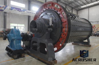
mining circuit diagram for robot manufacturer Grasping strong production capability, advanced research strength and excellent service, Shanghai mining circuit diagram for robot supplier create the value and bring values to all of customers.
 WhatsApp)
Proximity detector circuit. Below is the circuit of the proximity sensor for path-tracking robots. The circuit makes use of proximity sensors IR LED3 through IR LED6, voltage regulator LM7805 (IC2), motor-driver IC L293D (IC3), two geared motors/DC motors, 12V DC adaptor and two wheels. Voltage regulator IC2 converts the 12V DC into 5V DC.

The robot is designed to detect intensity of fire and operate first at place where the intensity of fire is more. It is also an automatic robot as it does not need to be operated from any remote control. One only needs to deploy the robot in a fire prone zone and the robot will automatically initiate action once it detects a fire breakout.
Dec 10, 2017· The aim of this project is to implement an obstacle avoiding robot using ultrasonic sensor and Arduino. All the connections are made as per the circuit diagram. The working of the project is explained below. When the robot is powered on, both the motors of the robot will run normally and the robot moves forward.

DESIGN STANDARDS ELECTRICAL SCHEMATIC DIAGRAMS Abstract This document provides standards for all electrical schematic diagrams for the LHC and its detectors. It covers:! High and low voltage distribution diagrams.! Relay and automatism diagrams.! Lighting, power and earth protection diagrams.! LHC main ring magnets cabling diagrams.

Circuit Diagram A circuit diagram (also named electrical diagram, elementary diagram, electronic schematic) is a graphical representation of an electrical circuit. Circuit diagrams are widely used for the circuit design, construction, and maintenance of electrical and electronic equipment.
Wireless RF Controlled LPG Detecting Robot for underground and mining Applications LPG Detecting robots play vital role in Natural Gas and LPG based process industries. This robot is controlled by an RF remote. This can be moved forward and reverse direction using geared motors of 60RPM. Also this robot can take sharp turnings

ABB Training Manual No. 2: Emergency Stops 4 Section 2 – Basic Training Product definition An Emergency Stop is defined as a fail-safe control switch or circuit that, when de-energized, will stop the operation of associated equipment and will shut off all potential hazards

Robots can be fixed robots or mobile robots. Mobile Robots are robots with a mobile base which makes the robot move freely in the environment. One of the advanced mobile robots is the Line Follower Robot. It is basically a robot which follows a particular path or trajectory and decides its own course of action which interacts with obstacle.

Oct 15, 2017· Hey friends in this tutorial I will show you how to make a voice controlled robot / car with Arduino. Visit my Website to Download Codes and Circuit Diagrams...

Aug 11, 2015· Block Diagram for DTMF Controlled Robot using Arduino. Remote section: This section's main component is DTMF. Here we get a tone from our cellphone by using aux wire to DTMF Decoder IC namely MT8870 which decodes the tone into digital signal of 4bit.

This circuit describe a simple obstacle avoiding robot which a you can easily make in your homes because it does not contains any complex digital circuitry and this can be made without using any microcontroller. This is an intelligent robot which will automatically detect the presence of obstacle in its path and change the direction of motion accordingly.
This robot consists of mainly two sections. They are explained in detail below. Remote Control Operated Spy Robot Circuit – Block Diagram 1. Remote Control Section The circuit uses HT 12E, HT 12D encoder and decoder. 433MHz ASK transmitter and receiver is used for the remote control. H-bridge circuits are used for driving motors.
Aug 21, 2015· Circuit Diagram for RF Receiver: As shown in above figures, circuit diagrams for RF controlled robot are quite simple where a RF pair is used for communication. Connections for transmitter and receiver show in circuit diagrams. Two 9 volt batteries are used to power the motor driver and remaining Rx Circuit. And another 9 Volt battery is used ...
Yaskawa's Z1000 variable speed drive is designed for building automation applications such as fans, pumps, and cooling towers through 500HP.
Controllers Product Article numbers for circuit diagrams Circuit diagram - IRC5 3HAC024480-011 Circuit diagram - IRC5 Compact 3HAC049406-003 Circuit diagram - IRC5 Panel Mounted Con- 3HAC026871-020 troller Circuit diagram - Euromap 3HAC024120-004 Circuit diagram - Spot welding cabinet 3HAC057185-001 Robots...

9 mine diagrams. Any self respecting geek who has been spellbound by the inspired rescue of the Chilean miners, will have found plenty of great info-graphics showing just how impressive a mine is.

Factorio is a game in which you build and maintain factories. You will be mining resources, researching technologies, building infrastructure, automating production and fighting enemies. In the beginning you will find yourself chopping trees, mining ores and crafting mechanical arms and transport belts by hand, but in short time you can become an industrial powerhouse, with huge solar fields ...

For more information about how the robot works and what the different parts of the circuit do, continue reading the rest of the Introduction. For a detailed explanation of the robot's circuit (for advanced students or robotics/electronics hobbyists), including a complete circuit diagram, see the Help section.

Hazardous Gas Detecting Rescue Robot in Coal Mines 71 Fig 1: The schematic diagram of the robot. Fig 2: Top view of the robot. Fig 1: Bottom view of the robot.. Move on level B. Mechanical Design The robot has dimension (500x320x130) mm which is the length, width, and .

Linear LED driver circuit diagram 30V adjustable current: Ambient LED light circuit diagram driver: TRIAC Dimmable LED Driver 14 W circuit diagram: LED Flasher circuit diagram with Luxeon V Star LED: 1.5V battery cell LED flasher circuit diagram: Non-Isolated LED Lighting circuit diagram Off .

Dec 20, 2017· Circuit Diagram: The complete circuit diagram for this Fire Fighting Robot is given below. You can either connect all the shown connections for uploading the program to check the working or you can assemble the bot completely and then proceed with the connections. Both ways the connections are very simple and you should be able to get it right.

Line Following Robot With PID Algorithm: Line following robot designed with Solidworks and implemented with arduino, ardumoto for control of the wheels, and a sensor bar with 8 infrared sensors. For any questions regarding this line following please leave a comment or message me.
URCaps induction (Circuit diagrams) Project: Documentation Robot and induction soldering
4.1.2 Circuit diagram 19 4.1.3 Connection of feeder cables 20 4.2 Configuration of Welding Equipment 24 4.2.1 General 24 4.2.2 Installation disk 24 ... A robot is heavy and extremely powerful regardless of its speed. A stoppage or longer stop can be followed by rapid, dangerous movements. Even if the robot's
WhatsApp)